LangGraph 底层原理:它是怎么把 LLM 变成一台状态机的
LangGraph 底层原理:它是怎么把 LLM 变成一台状态机的
为什么同样是调用 LLM,用了 LangGraph 之后,AI 就能「想一步、停一步、判断一步」?就能在工具调用和 LLM 推理之间来回切换,还不会乱套?
答案就藏在它的状态机设计里。
01 先说说 LangChain 的老问题
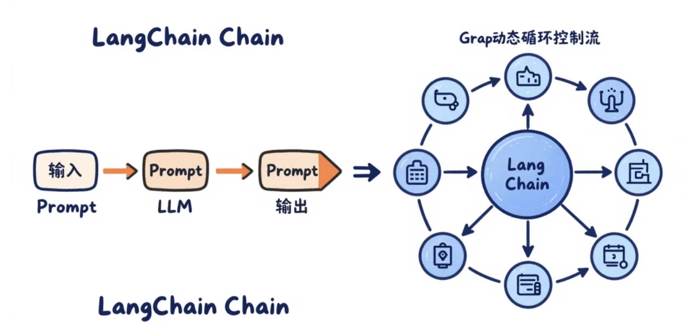
LangChain 的早期架构是线性的——Chain。
用户输入→PromptTemplate→LLM→OutputParser→输出
这个模型干净利落,但有个致命弱点:控制流是固定的。
一旦你想实现「如果 LLM 觉得需要查数据库就查,不需要就跳过」,或者「出错了重试三次」,你会发现原来的 Chain 根本放不下这些逻辑。要么把判断逻辑硬编码在节点里,要么用 Python 的 if/else 在外层手动管流程——乱成一锅粥。
现实中的 Agent 场景根本不是线性的:
- 调工具 → 看结果 → 决定调下一个还是直接回答
- 生成草稿 → 自我审查 → 不行就重写
- 多轮对话 → 根据意图走不同分支
这些都需要带状态的循环控制流。这正是 LangGraph 解决的核心问题。
02 状态机是什么:用最简单的例子解释
状态机(State Machine)不是什么新概念。你手机的蓝牙就是个状态机:
[关闭]--打开-->[扫描中]--发现设备-->[配对中]--成功-->[已连接]
                                       |
                                       └--失败-->[扫描中]
三个核心要素:
┌─────────────────────────────────────────────┐
│              状态机三要素                     │
├──────────┬──────────────────────────────────┤
│  State   │ 当前的数据快照(系统处于什么情况)    │
│   Node   │ 执行动作,并更新 State              │
│   Edge   │ 决定下一步去哪个 Node               │
└──────────┴──────────────────────────────────┘
LangGraph 就是把这套机制套在了 LLM 上:
- State = 对话历史 + 工具结果 + 中间变量
- Node = LLM 调用 / 工具执行 / 业务逻辑
- Edge = 普通跳转 / 条件分支(Conditional Edge)
03 StateGraph 执行引擎:它的心脏长什么样
打开 LangGraph 的源码(Python 版 langgraph/graph/state.py,JS 版同理),你会看到 StateGraph 类维护了几个核心数据结构:
┌──────────────────────────────────────────────────┐
│              StateGraph 内部结构                  │
├─────────────────┬────────────────────────────────┤
│     nodes       │    Map<名称,函数>             │
│     edges       │    Map<from, to[]>            │
│ conditional_    │    Map<from, (state)=>节点名> │
│     edges       │                                │
│ channels/       │    每个状态字段的 Reducer      │
│     schema      │                                │
└─────────────────┴────────────────────────────────┘
当你调用 graph.compile() 时,它做了什么?
compile() 阶段
│
├─ 验证图结构(有没有孤立节点?有没有到 END 的路径?)
├─ 构建邻接表(预计算每个节点的后继)
├─ 初始化 Channels(每个状态字段注册 Reducer)
└─ 返回 CompiledGraph(可以 invoke/stream)
compile() 本质上是把你「描述的图」变成「可执行的调度器」。
04 一次完整执行:从 invoke 到节点运行的全流程
来看最简单的例子,一个单节点 LLM Agent:
import { StateGraph, START, END } from "@langchain/langgraph";
import { Annotation } from "@langchain/langgraph";
import { ChatOpenAI } from "@langchain/openai";
import { HumanMessage } from "@langchain/core/messages";

// 1. 定义状态结构
const AgentState = Annotation.Root({
  messages: Annotation<HumanMessage[]>({
    reducer: (prev, next) => [...prev, ...next],
    default: () => [],
  }),
});

// 2. 初始化 LLM
const llm = new ChatOpenAI({ model: "gpt-4o-mini" });

// 3. 定义节点函数
async function callLLM(state: typeof AgentState.State) {
  const response = await llm.invoke(state.messages);
  return { messages: [response] };
}

// 4. 构建图
const graph = new StateGraph(AgentState).addNode("agent", callLLM).addEdge(START, "agent").addEdge("agent", END).compile();
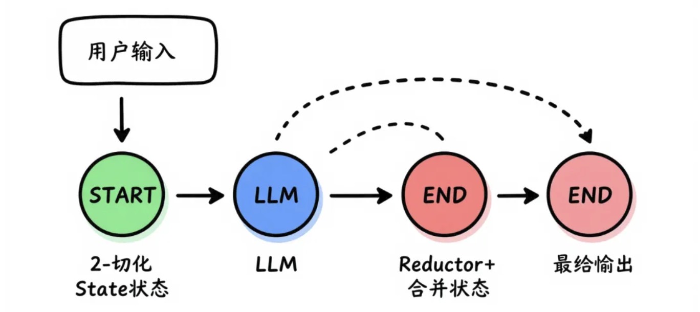
执行流程:
invoke(input)
│
├─ 初始化 State = { messages: [input] }
├─ 从 START 节点出发
├─ 查找后继节点 → "agent"
├─ 执行 callLLM(state)
│  └─ LLM 返回 response
│  └─ 返回 { messages: [response] }
├─ Reducer 合并状态:prev=[input], next=[response] → [input, response]
├─ 查找后继节点 → END
└─ 返回最终 State
05 Reducer:状态更新的核心机制
每个状态字段都有一个 Reducer 函数,定义如何合并新旧值:
// 三种常见 Reducer 写法

// 方式1:用内置 messagesStateReducer(追加消息)
const State1 = Annotation.Root({
  messages: Annotation<BaseMessage[]>({
    reducer: (prev, next) => [...prev, ...next],
  }),
});

// 方式2:覆盖(最新值覆盖旧值)
const State2 = Annotation.Root({
  step: Annotation<number>({
    reducer: (_, next) => next, // 直接替换
  }),
});

// 方式3:累加计数
const State3 = Annotation.Root({
  callCount: Annotation<number>({
    reducer: (prev, next) => prev + next,
    default: () => 0,
  }),
});
Reducer 的执行时机:
节点返回 { key: value }
         │
         ▼
  对每个 key,找到对应 Reducer
  newState[key] = reducer(oldState[key], value)
         │
         ▼
  生成新 State 快照
  (旧 State 不变,不可变数据结构)
常见的 Reducer 模式:
- 追加模式:
[...prev, ...next]—— 适用于对话历史 - 覆盖模式:
next—— 适用于临时变量 - 最小值模式:
Math.min(prev, next)—— 适用于计数/阈值 - 自定义合并:深度合并对象
06 图的调度器:它怎么决定下一步去哪
有两种边:
-
普通边(Normal Edge):固定跳转
.addEdge("nodeA", "nodeB") // nodeA 执行完必去 nodeB -
条件边(Conditional Edge):根据状态动态选择
function route(state: State): "nodeB" | "nodeC" {
  if (state.needsTool) return "nodeB";
  return "nodeC";
}
.addConditionalEdges("nodeA", route)
调度器的工作流程:
当前节点执行完成
│
├─ 如果有条件边 → 调用 route 函数 → 决定下一个节点
├─ 如果有普通边 → 直接跳到目标节点
├─ 如果有多个后继 → 并行执行(见下一节)
└─ 如果到达 END → 返回结果
graph TD
    A[节点执行完成] --> B{有边类型?}
    B -->|条件边 | C[调用 route 函数]
    C --> D[决定下一个节点]
    B -->|普通边 | E[直接跳到目标节点]
    D --> F[执行下一个节点]
    E --> F
    F --> G{到达 END?}
    G -->|是 | H[返回结果]
    G -->|否 | A

    style C fill:#e3f2fd
    style H fill:#e8f5e9
07 并行执行:Fan-out / Fan-in 模式
LangGraph 支持并行执行多个节点,典型场景是「同时调用多个工具」。
Fan-out:一个节点分发到多个并行节点
Fan-in:多个并行节点汇聚到一个节点
// Fan-out: 同时调用搜索和计算器
graph.addNode("search", callSearchTool).addNode("calculator", callCalculatorTool).addEdge("agent", "search").addEdge("agent", "calculator");

// Fan-in: 等待两者都完成后再聚合
graph.addNode("aggregate", aggregateResults).addEdge("search", "aggregate").addEdge("calculator", "aggregate");
并行执行时,调度器会:
- 启动所有后继节点
- 等待所有节点完成(或设置超时)
- 将所有返回值合并到状态中
graph LR
    A[agent] --> B[search]
    A --> C[calculator]
    B --> D[aggregate]
    C --> D

    style A fill:#fff3e0
    style B fill:#e3f2fd
    style C fill:#e3f2fd
    style D fill:#e8f5e9
08 编译产物:CompiledGraph 里藏了什么
当你调用 compile() 后,得到的是一个 CompiledGraph 对象。它包含:
- 执行图(Execution Graph):预计算的邻接表
- 状态通道(State Channels):每个字段的 Reducer 注册
- 调度器(Scheduler):运行时决策逻辑
- 检查点(Checkpoints):支持持久化和恢复(可选)
const compiled = graph.compile();

// 内部结构
compiled.nodes = { "agent": callLLM, "search": callSearchTool, ... };
compiled.edges = { START: ["agent"], "agent": ["search", "calculator"], ... };
compiled.channels = { "messages": MessageChannel, ... };
编译后的图可以直接 invoke、stream 或 subscribe:
// 一次性执行
const result = await compiled.invoke({ messages: [input] });

// 流式输出
for await (const step of compiled.stream({ messages: [input] })) {
  console.log(step);
}
总结
LangGraph 的核心贡献在于:
- 状态机抽象:把 LLM 从「一次性推理」变成「可循环、可分支、可暂停」的状态机
- Reducer 机制:安全、灵活的状态更新策略
- 条件边:动态决策,支持复杂 Agent 逻辑
- 并行执行:Fan-out / Fan-in 模式,提升工具调用效率
- 编译优化:预计算图结构,运行时高效调度